Hello Again!
Over the past years I have been making PCBs by just watching it etch away. Sometimes I would heat up the chemicals in the microwave, jiggle it around manually, use a stirrer, or a straw to facilitate the etching process.
You all probably know that by agitating the etchant, it etches faster. I don't throw out etchant that often (in fact I have never), so my it gets old, colorful, and ineffective.
Since I do not want to manually agitate, I decided to have an automatic agitator. There are many designs out there already.
Here are some just to name a few:
Microcontroller and H-bridge: http://indiantinker.wordpress.com/2013/09/04/open-agitator/
Arduino and H-bridge: http://www.instructables.com/id/CD-ROM-Agitator/
555, 4017, 4 transistor H-bridge: http://www.instructables.com/id/PCB-agitator-from-an-old-CR-ROM/
I wanted to build one of these, but I did NOT want to use $30 hardware (Arduino) to do a simple back and forth motion, and I did NOT want to deal with the crazily pinned 4017 decade counter.
Seriously.
Look at the pinout of LM4017. It's crazy and not easy to play with.

Can't you just put Q0-Q7 in order?
So, I really simplified the design.
First of all, I would not have done this without the guys on the Arduino Forum.
I would like to give a special thanks to michiyon, TomGeorge, JohnLincoln, MarkT, MAS3, polymorph, and cjdelphi
My circuit was originally not functional, but I got help. Click the link if you want to see the debug process.
So, here is the schematic.
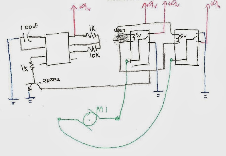
There are many things you can do to change this for it to work better, for example,
- connecting pin 4 on 555 to 9v
- connecting pin 5 to 0.1 uf capacitor to ground
- connecting the relay coils in series than in parallel
- probably many other things I am forgetting
The reason I did not add these were for simplicity. This is the bare circuit.
You need:
- 100 uf capacitor
- 2*1k resistor
- 10k resistor
- 2*5v relay
- 9v battery and clip
- 2n2222 transistor or the like
- CD drive
- 4007 power diode (or the like)
Here is how I assembled it:

Two relays taped together. The two SPDT relays with the same coil connect make a DPDT relay to function as an H-bridge.

Tight soldering!
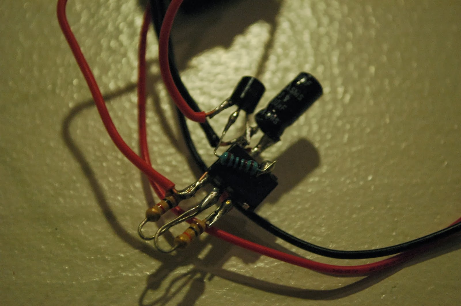
The 555 timer
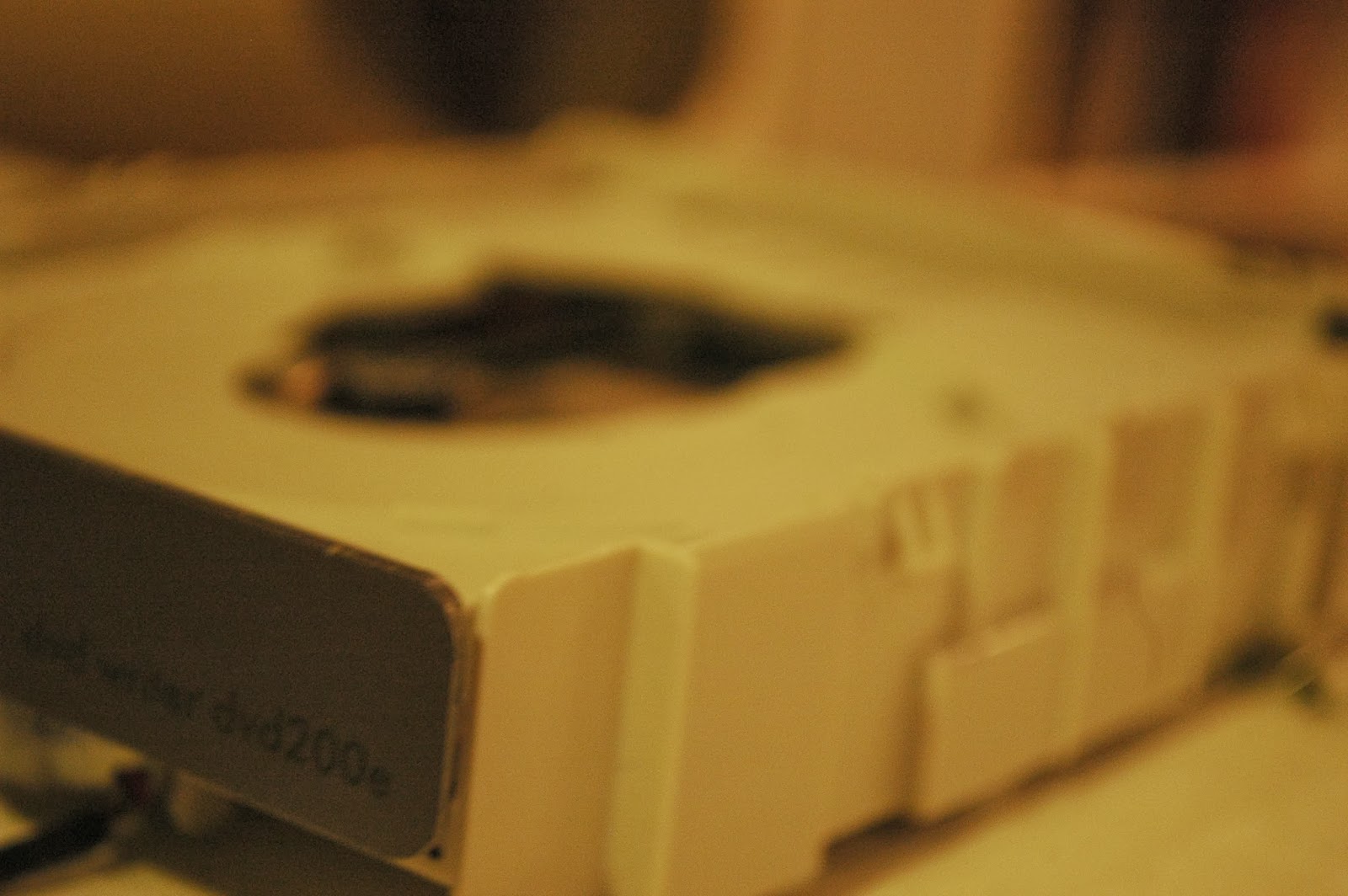
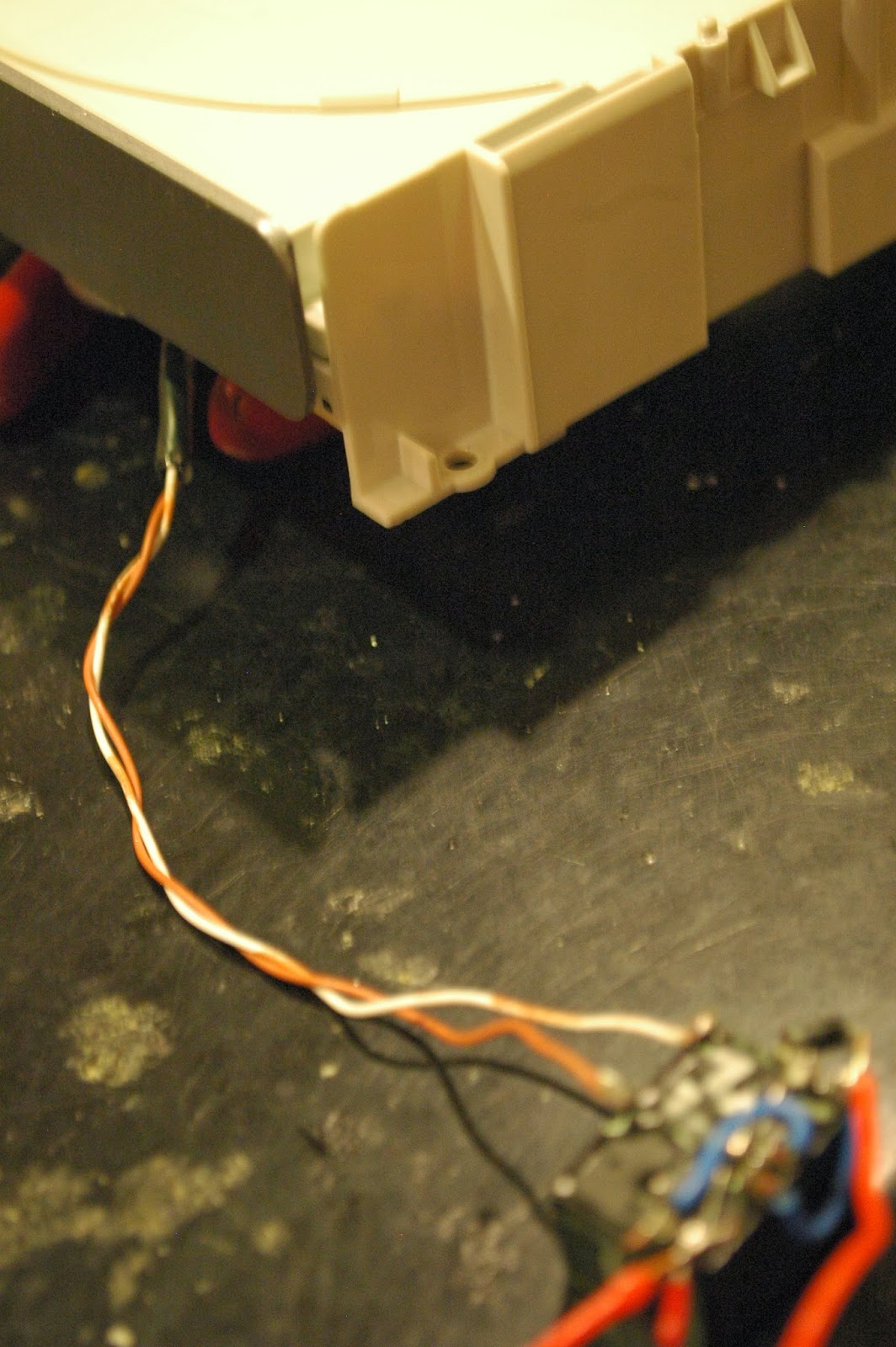
Taken apart CD drive.
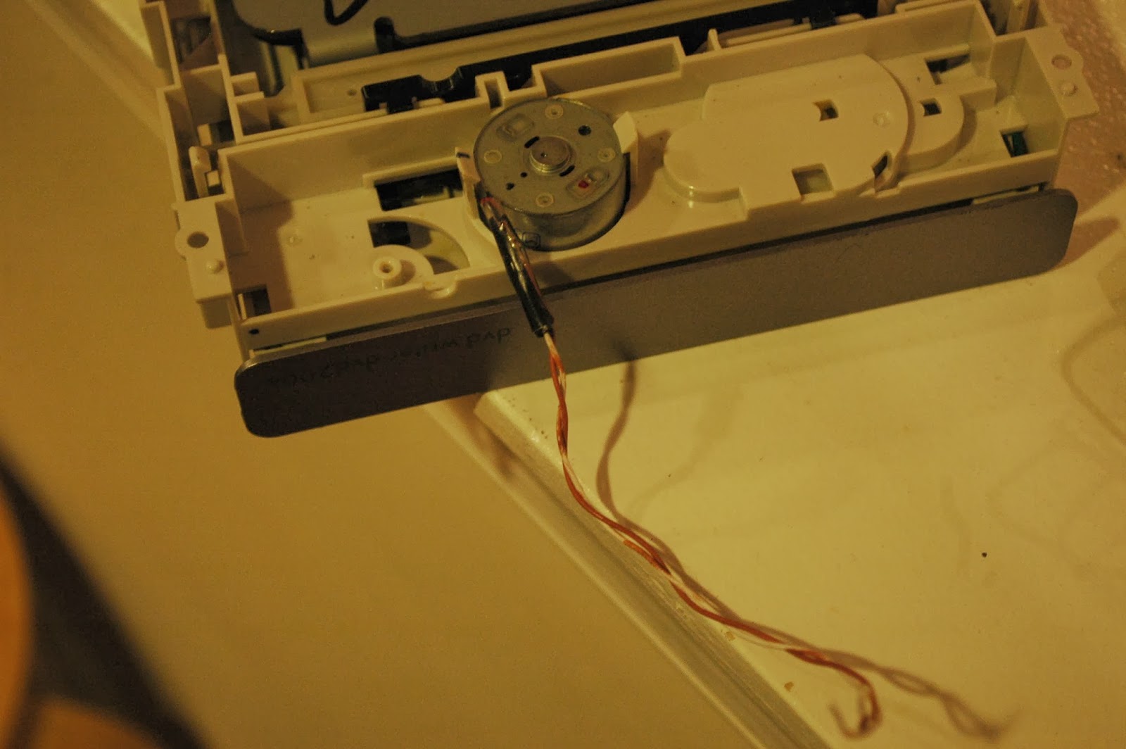
The motor for the eject.
Here is a video:
It is a bit kicky, probably because of a current issue, but it works for now.
And it's a lot cheaper than the other PCB agitators, using less parts :D
I hope you enjoy it.
No comments:
Post a Comment